Product Description
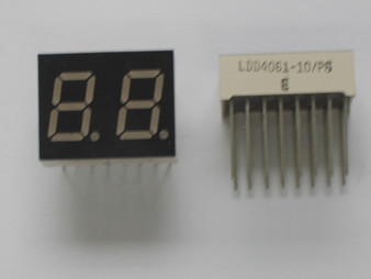
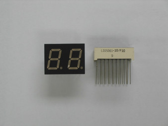
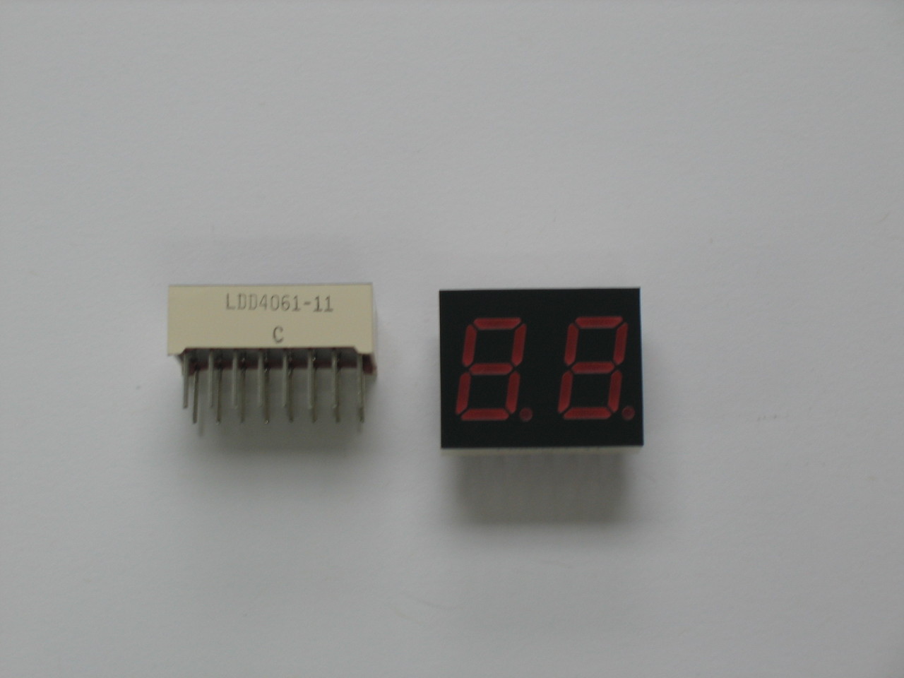
Galaxy / Cobra Red 2-Digit LED Channel Display Segment (Part # EX03N40548 / EX03N40003)
Restore sharp, high-contrast, non-fading channel readout visibility across classic Galaxy, Ranger, Cobra, and Mirage transceivers with this genuine OEM-spec Red 2-Digit 7-Segment LED Channel Display Assembly. Sourced under updated Galaxy part number EX03N40548 (supersedes legacy part number EX03N40003 and component designations LDD4061-11 / XIN-DD204RC01-04; Cobra part number 238-007-N-001), this original 2-digit display unit delivers precise pinout alignment and bright red segment illumination for legacy 27 MHz / 10-meter chassis.
Product Specifications & Technical Data
- Manufacturer Part Number: EX03N40548 (Supersedes EX03N40003)
- Cross-Reference / Component Part Numbers: LDD4061-11, XIN-DD204RC01-04, Cobra # 238-007-N-001
- Component Type: Factory 2-Digit 7-Segment LED Channel Indicator Module
- Emitted Color: High-Visibility Red (~635nm)
- Circuit Schematic Function: Visual 2-digit channel selection display driven by logic decoder/PLL display drivers
- Mounting Configuration: Multi-Pin DIP Through-Hole Solder Mount PCB Header
- Quality Standard: 100% Factory Original Equipment Manufacturer (OEM) service replacement component
- Compatible Radio Models & Chassis:
- Galaxy Models: DX33V, DX44V, DX77HML, and related red-display mobile transceivers
- Ranger Models: RCI-6300, RCI-6900, TR-296
- Mirage Models: MX-86HP
- Cobra Models: 148F GTL, 148F GTL-DX, and chassis using Cobra part # 238-007-N-001
Installation & Bench Notes
- Diagnoses & Solves: Missing or dead LED segments (e.g., partial numbers), dim channel display, flickering digits, or wrong channel segment encoding caused by burnt internal LED diodes.
- BENCH INSTALLATION PROCEDURE:
- Disconnect DC power supply leads from the transceiver chassis and discharge internal filter capacitors before servicing.
- Remove top and bottom cabinet covers and loosen front panel bezel mounting screws to gain access to the display PCB assembly.
- Desolder all pins of the defective 2-digit display using a temperature-controlled desoldering iron with vacuum suction or desoldering braid, taking care not to lift fragile PCB solder pads or traces.
- Clean the through-hole mounting pads on the display PCB with isopropyl alcohol.
- Align the pin configuration and decimal orientation of the new EX03N40548 display module precisely with the board silkscreen layout.
- Solder all display pins securely using 63/37 eutectic solder, ensuring clean solder joints without solder bridges between adjacent pins.
- Power on the unit and rotate the channel selector switch through all channels (1-40) to verify 100% segment illumination and clear digit formation.