Product Description
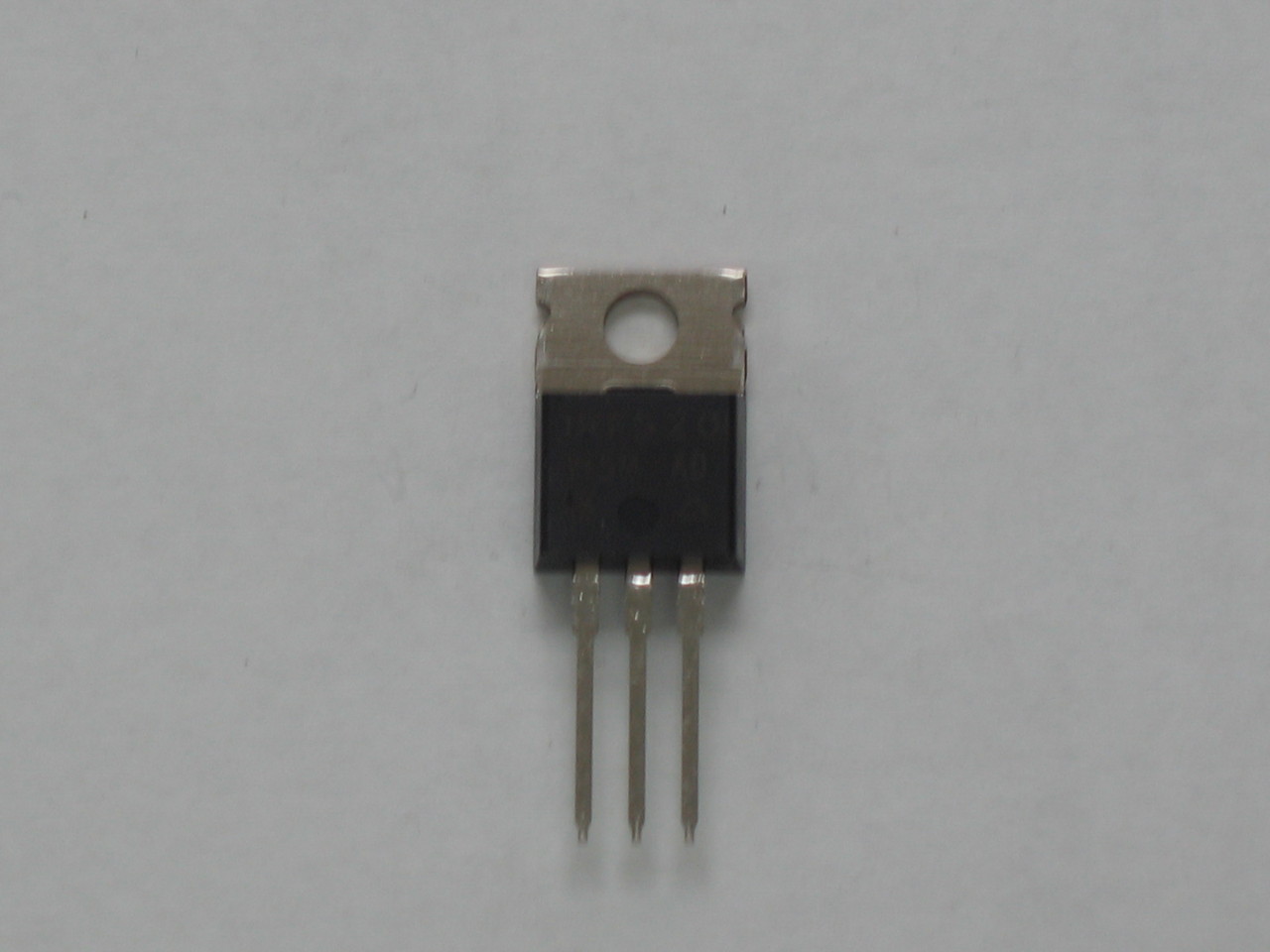
Ranger / Vishay IRF520 Power N-Channel MOSFET Transistor (Part # TIRF00520ZR / IRF520PBF)
Restore clean, reliable RF output power and fast switching efficiency to your transceiver with this genuine, factory-original Vishay IRF520 Power N-Channel MOSFET. Sourced directly from Ranger, this authentic OEM transistor (Part # TIRF00520ZR / IRF520PBF) provides the exact breakdown voltage, gate charge characteristics, and thermal performance required for high-frequency driver and final RF amplifier stages in modern Galaxy and Ranger mobile radios.
Product Specifications & Compatibility
- Ranger OEM Part Number: TIRF00520ZR
- Manufacturer Part Number: Vishay IRF520PBF (Pb-Free / RoHS Compliant)
- Transistor Type: High-Performance N-Channel Power MOSFET
- Package Style: TO-220AB (Heavy-Duty Metal Tab Package)
- Key Electrical Ratings: Drain-Source Voltage ($V_{DS}$): $100\text{V}$ | Continuous Drain Current ($I_D$): $9.2\text{A}$ | Low On-Resistance ($R_{DS(\text{on})}$): $0.27\,\Omega$
- Compatible Radio Models: Ranger, Galaxy, Connex, and Super Star transceivers utilizing factory MOSFET driver or final amplifier stages (including MOSFET-converted EPT3600 and EPT055 mainboard series)
Bench Installation & Tech Notes
- Replaces shorted, open, or thermally degraded driver/final MOSFETs caused by high SWR, improper antenna tuning, or excessive drive levels.
- Beware of Counterfeits: Counterfeit and low-grade knockoff IRF520 MOSFETs plague the aftermarket, leading to rapid gate breakdown or severely degraded RF wattage. These are 100% original Vishay parts supplied directly by Ranger to guarantee factory spec performance.
- Mica Insulator & Thermal Compound: Always install a fresh mica insulating washer (or thermal pad) and apply non-conductive thermal grease between the TO-220 metal tab and the chassis heatsink. Verify complete electrical isolation (infinity $\Omega$) between the transistor drain/tab and chassis ground before applying DC power to prevent immediate short circuits.
- Gate Drive & Bias Setting: When replacing blown MOSFETs, inspect associated gate protection diodes, bias supply zener diodes, and low-value gate resistors for drift or failure. Re-check idle bias voltage at the gate pad according to factory service manual guidelines prior to full modulation testing.