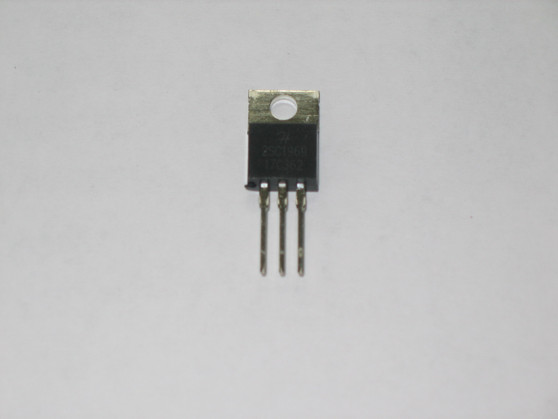
Product Description
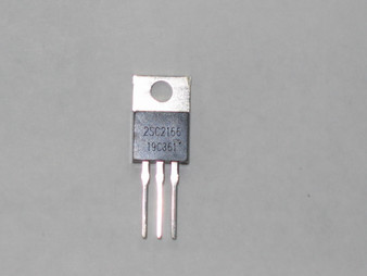
Ranger OEM / HG Semiconductor 2SC1969 NPN Epitaxial Planar RF Power Transistor (Part # HG2SC1969)
Restore full high-frequency RF output power and modulation peaks across classic AM/SSB mobile transceivers with this genuine factory-sourced HG Brand 2SC1969 NPN Epitaxial Planar Transistor. Sourced directly through Ranger Communications, these high-power replacement devices are manufactured by Huagao Semiconductor Co. (HG Brand) specifically to replace discontinued Mitsubishi 2SC1969 inventory, delivering reliable 12-volt RF power amplifier performance up to 30 MHz in TO-220AB package configurations.
Product Specifications & Technical Data
- Manufacturer / Brand: Huagao Semiconductor Co. (HG Brand) — Sourced Direct from Ranger Communications
- Factory Part Number: HG2SC1969 / HG 2SC1969
- Device Type: NPN Silicon Epitaxial Planar RF Power Transistor
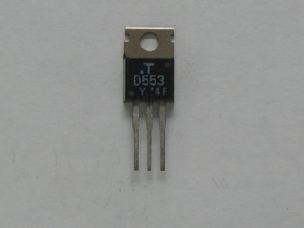
- Package Style: TO-220AB (Standard Metal Tab Heat Sink Configuration)
- Frequency Range & Target Band: 27 MHz / 10-Meter HF Spectrum (Designed for 12V DC Class AB & Class C RF Amplifiers)
- Pinout Alignment: Standard TO-220 RF Pinout: Pin 1: Base | Pin 2: Collector (Tab) | Pin 3: Emitter
- Technical Manufacturer Note: Sourced directly from Ranger as an authorized service replacement. Not manufactured by Mitsubishi Electric; branded as HG Semiconductor.
- Compatible Radio Models & Chassis:
- Ranger & RCI Models: RCI-2950, RCI-2970 (Driver/Final Stages), and related 10-meter platforms
- Galaxy & Connex Models: DX33HP, DX44V, DX55V, DX66V, DX77HML, DX88HL, DX99V, DX949, DX959, and related AM/SSB mainboards
- Cobra & Uniden Chassis: Cobra 29 LTD, Cobra 148 GTL, Uniden Grant LT, and EPT3600-based transceivers utilizing TO-220 RF final stages
Installation & Bench Notes
- Diagnoses & Solves: Blown RF final stage (zero RF power output on transmit), dead carrier with normal receive, shorted collector tab tripping power supply protection, or degraded modulation envelope due to thermal damage.
- BENCH INSTALLATION PROCEDURE:
- Disconnect DC power supply leads from the transceiver chassis and ensure internal high-current supply capacitors are fully discharged.
- Desolder the damaged final transistor leads from the main RF power section using a temperature-controlled soldering iron and desoldering braid.
- Remove the mounting screw securing the transistor tab to the chassis heat sink, carefully retaining the mica insulating washer and nylon shoulder insulator bushing.
- Clean the heat sink mounting surface thoroughly with high-purity isopropyl alcohol to remove dried thermal compound and metal burrs.
- Apply a fresh, uniform layer of non-conductive zinc-oxide thermal grease to both sides of the mica insulator.
- Mount the new HG2SC1969 transistor with its mica insulator and nylon shoulder washer to the heat sink wall. Tighten the retaining screw snugly before soldering leads to prevent mechanical strain on the PCB copper pads.
- Verify with an ohmmeter that there is NO electrical continuity between the collector tab (Pin 2) and the chassis ground.
- Solder the Base, Collector, and Emitter leads using 63/37 eutectic solder.
- Apply power, key the transmitter into a 50-ohm dummy load, and adjust SSB driver/final bias currents per the factory alignment manual to ensure clean, distortion-free RF transmission.