


Product Description
Galaxy Red 2-Digit LED Channel Display Segment (Part # PTDX55020B) for High-Power DX93T / DX95T Transceivers
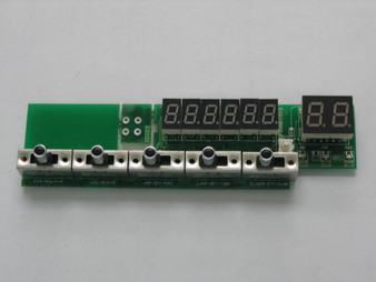
Restore razor-sharp, high-contrast red channel readout visibility across high-power Galaxy HP-series mobile transceivers with this genuine OEM-spec Red 2-Digit 7-Segment LED Channel Display Assembly. Sourced under original part number PTDX55020B, this heavy-duty 2-digit display unit delivers precise pin alignment, matched forward voltage drop, and high-intensity red segment output specifically engineered for high-power platforms like the Galaxy DX93T and Galaxy DX95T.
Product Specifications & Technical Data
- Manufacturer Part Number: PTDX55020B
- Component Type: Factory 2-Digit 7-Segment LED Channel Indicator Module
- Emitted Color: High-Visibility Red (~635nm)
- Circuit Schematic Function: Visual 2-digit channel selection indicator driven by display decoder logic on the front-panel control sub-board
- Mounting Configuration: Multi-Pin Through-Hole DIP Solder Mount PCB Header
- Quality Standard: 100% Factory Original Equipment Manufacturer (OEM) service replacement component
- Compatible Radio Models & Chassis:
- Galaxy High-Power Mobile Models: Galaxy DX93T, Galaxy DX95T, DX93T2, DX95T2, and related red-display high-power mobile platforms
- Select Ranger, RCI, and Superstar high-power chassis requiring the PTDX55020B red 2-digit channel display sub-board module
Installation & Bench Notes
- Diagnoses & Solves: Missing or dead LED segments (partial digit readout), dim display digits, flickering numbers, or wrong segment decoding caused by internal LED diode junction failure from heat or age.
- BENCH INSTALLATION PROCEDURE:
- Disconnect DC power supply leads from the transceiver chassis and ensure internal high-current power supply capacitors are completely discharged.
- Remove top and bottom cabinet covers and loosen front panel bezel mounting screws to gain access to the display PCB sub-board.
- Desolder all interface pins of the defective 2-digit display module using a temperature-controlled desoldering iron with vacuum suction, taking care not to overheat or lift fragile copper PCB pads.
- Clean through-hole solder pads thoroughly with high-purity isopropyl alcohol and desoldering braid.
- Align the pin header configuration and decimal orientation of the new PTDX55020B display module precisely with the board silkscreen layout.
- Solder all display pins securely using 63/37 eutectic solder, verifying clean solder joints without shorting bridges between adjacent pins.
- Power on the unit and switch through all channels to verify 100% segment illumination and clear digit formation across all operating bands.